
Cross-sections allow the vertical dimensions of a noise model to be speedily examined in detail. This includes vertical noise contours.
You select the cross-section function and then click on any number of way-points along the cross-section. You can also create long-sections of roads, railways, etc.
In the following example, there is a road bridge over a railway. It is hard to see the height of the various elements in the plan view below:
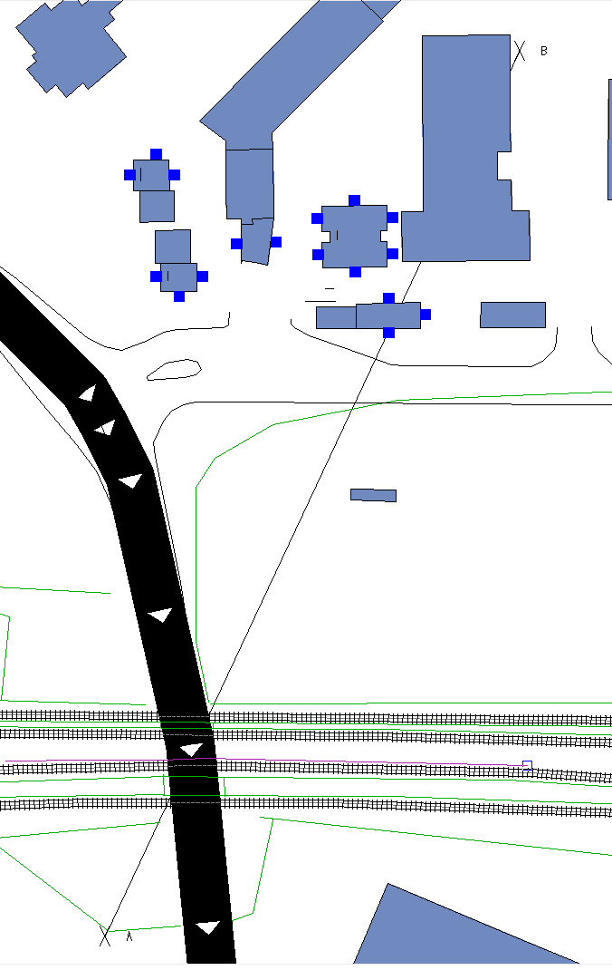
However, by drawing a cross-section from A to B, it becomes clear:
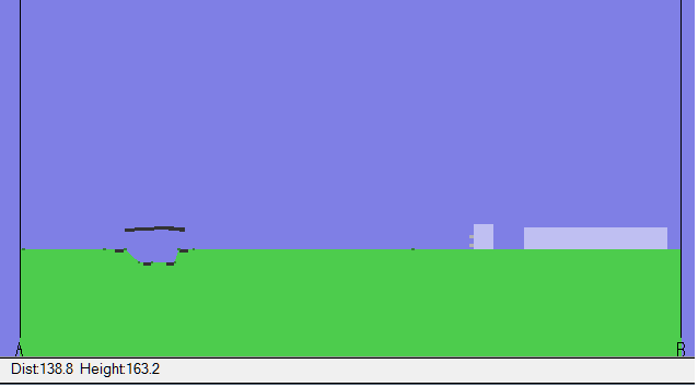
Now we can see that two of the railway lines are in a cutting but two are at ground level, and the road crosses them all on a bridge.
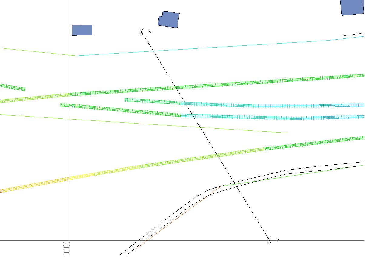
In another part of the same example, the railway lines cross on a ‘grade -separated’ junction (a flyover). In the diagram below, we use ‘View-As-Colour’ which shows that two lines are lower (bluish colours) and pass beneath a line that is higher.
However, the cross-section makes this and the ground levels much clearer:
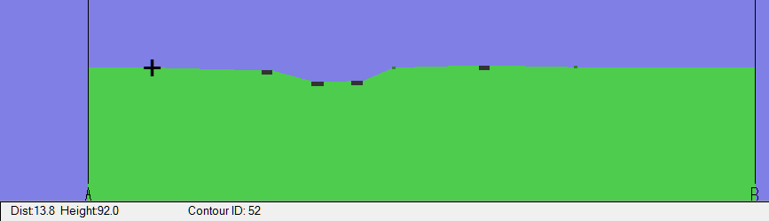
Note on this cross-section, the cursor has been positioned over a contour line (shown as small green squares in the section) and the readout at the bottom of the section shows both the contour number and its height. The ability to identify objects in this way helps to check and correct for errors.